
Current Transformers (CT) Explained
A feeder can carry 2000A. No relay or meter is built to touch that directly. A current transformer is the sensor that makes protection and metering possible in the first place — and it has one safety rule every engineer learns early.
What a current transformer actually does
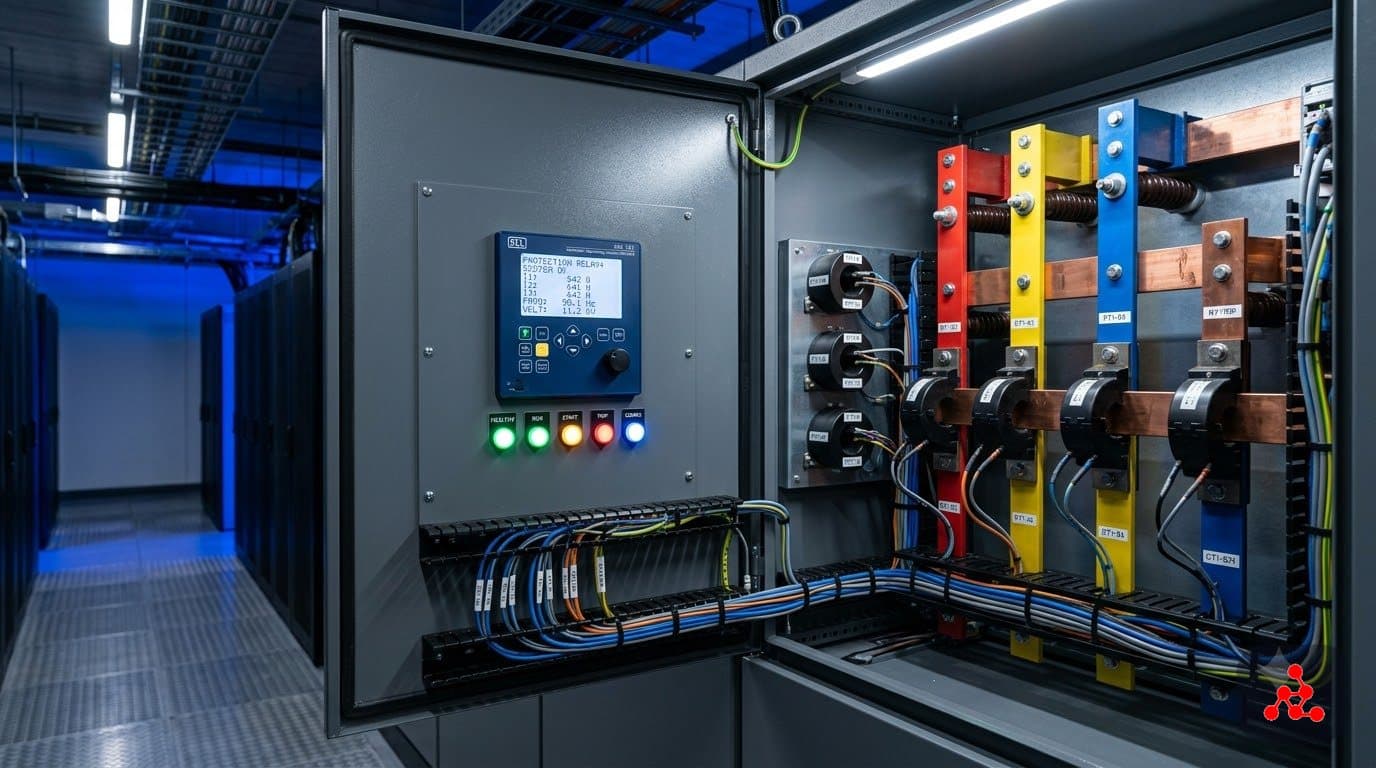
A CT clamps around (or is built into) a primary conductor and steps a large current — say, 2000A flowing through a feeder — down to a small, standardized secondary current, commonly 5A or 1A, at a fixed ratio marked on the CT nameplate (for example, "2000/5"). That secondary current is what actually feeds ammeters, energy meters, and protection relays, regardless of how large the real primary current is. Without that scaling, no standard relay or meter could survive being connected to the primary circuit at all.
Just as important as the current scaling is the electrical isolation a CT provides: the secondary circuit is galvanically separated from the primary, which is a safety requirement for anyone working on the low-voltage protection and metering wiring, not just a side benefit of the transformer action.
Metering CTs vs protection CTs
Not every CT is specified the same way, because metering and protection duty want different things from the same basic device. Metering CTs are built for high accuracy — commonly class 0.2 or 0.5 — specifically at normal load current, because that number feeds directly into billing. Protection CTs are built to stay linear and resist saturation even at many times rated current (commonly class 5P or 10P), because a relay needs an honest signal precisely during the overcurrent condition it exists to catch. It's routine for a single primary conductor to have separate CT cores — one for metering, one for protection — for exactly this reason.
Burden: the load a CT has to drive
A CT's "burden" is the total impedance its secondary has to drive: the wiring resistance plus every relay and meter connected to that circuit. Every CT has a rated burden it's designed to supply accurately. Exceed it — too much wire length, too many devices, undersized cable — and accuracy degrades, which is worst for protection CTs during a real fault, exactly when accuracy matters most.
The rule every engineer learns early: never open a live CT secondary
A CT secondary is designed to always see a low-impedance load. If that secondary is opened while primary current is still flowing — disconnecting a meter without shorting the CT first, for instance — the core loses the counter-mmf that keeps it operating in its normal, linear region and drives into heavy saturation. The result is a very high, potentially lethal voltage spike across the open terminals. The standard practice, whenever a CT-connected device needs to be removed from a live circuit, is to short the CT secondary first using a dedicated shorting link or terminal block — never leave it open.
Where CTs actually show up in a data center design
CTs appear at every level of the electrical distribution where something needs to be measured or protected: utility incomer metering, MV and LV feeder protection, transformer differential schemes (which need matched CT sets on both sides of the transformer), generator protection, and even busway and PDU-level monitoring in some designs. Reading a single-line diagram and correctly identifying which CTs feed metering versus which feed protection — and what ratio and class each one carries — is one of the first practical skills a new data center electrical designer builds.
Frequently Asked Questions
What happens if a CT secondary is left open-circuited while the circuit is energized?
It's genuinely dangerous. A CT is designed to always have a low-impedance load — a relay, a meter, or a shorting link — on its secondary. Open-circuit that secondary while primary current is flowing, and the core loses the counter-mmf that normally keeps it in its linear region, drives into heavy saturation, and induces very high, potentially lethal voltage spikes across the open terminals. If a meter or relay ever needs to be disconnected from a live CT, the secondary is shorted first, never left open.
What's the difference between a metering CT and a protection CT?
Metering CTs are built for high accuracy (commonly class 0.2 or 0.5) at normal load current, because that accuracy directly drives billing. Protection CTs are built to stay reasonably linear and resist saturation even at many times rated current (commonly class 5P or 10P), because a relay needs an honest signal specifically during the fault condition it's supposed to detect. It's common for a single primary conductor to have separate CT cores dedicated to each duty.
What does 'burden' mean for a CT?
Burden is the total impedance the CT secondary has to drive — the connected wiring plus every relay and meter on that circuit. Exceed the CT's rated burden and its accuracy degrades, which matters most for protection CTs during a fault, when the secondary current is highest and accuracy is most needed.
Why do CTs come with a fixed ratio like 2000/5 instead of a variable one?
The ratio is set by the physical design of the CT (primarily the number of secondary turns) and is fixed at manufacture, which is exactly what makes it a reliable, repeatable sensor — a relay or meter is calibrated against a known, unchanging ratio. Different ratios exist as different CT models sized to the expected primary current, not as an adjustable setting on one unit.
Want to learn this properly?
This topic is covered in depth in our Electrical Design – Data Center Specialist program.
Ask us on WhatsAppRead more: All articles or explore the Electrical Design – Data Center Specialist program, which covers protection and metering as a full module.