
Potential Transformers (PT/VT) Explained
A bus can sit at 11kV or 33kV. No relay or meter touches that directly. A potential transformer is the sensor that scales it down safely — and it comes with a safety rule that's the exact opposite of a current transformer's.
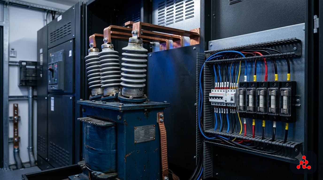
What a potential transformer actually does
A PT — also called a voltage transformer, or VT — steps a high primary voltage down to a small, standardized secondary voltage, commonly 110V or 100V line-to-line, at a fixed ratio marked on the PT nameplate. That secondary voltage is what actually feeds voltmeters, energy meters, protection relays, and synchronizing equipment, regardless of whether the real primary is 11kV, 33kV, or higher. Like a CT, a PT also provides electrical isolation between the high-voltage primary and the low-voltage secondary circuit — a safety requirement, not just a design convenience.
Wound PTs vs capacitor voltage transformers (CVTs)
At distribution voltages, most PTs are conventional wound (electromagnetic) transformers — a primary winding and a secondary winding around a common core, exactly like a power transformer but built for accuracy rather than power transfer. At transmission-class voltages, capacitor voltage transformers (CVTs) are often used instead: a capacitive divider steps the voltage down to an intermediate level before a small transformer finishes the job, which is more economical to build than a wound PT with an enormous turns ratio at that voltage class. Functionally, both deliver the same standardized low-voltage secondary signal.
Accuracy classes: metering vs protection, again
PTs follow the same metering-versus-protection split as CTs. Metering PTs are specified for high accuracy (commonly class 0.2 or 0.5) at normal system voltage, because that number drives billing. Protection PTs are specified with classes suited to reproducing voltage accurately even during system disturbances (commonly class 3P or 6P), because relays that watch for undervoltage, overvoltage, or directional faults need a trustworthy signal specifically when the system is stressed.
The rule every engineer learns early: never short a live PT secondary
This is the mirror image of the CT safety rule. A PT behaves like a voltage source on its secondary — short that secondary while the primary is energized, and very high current flows through the winding, which can damage the transformer or blow protective fuses in an instant. For exactly this reason, PT secondaries are almost always protected by dedicated fuses or miniature circuit breakers, and disconnecting a PT-fed device from a live circuit never involves shorting the secondary the way a CT does.
There's a subtler failure mode worth knowing too: ferroresonance, a nonlinear resonance that can develop between a wound PT's magnetizing inductance and stray or switching capacitance elsewhere in the network, producing abnormal overvoltages. It's a real, PT-specific phenomenon that influences PT selection and connection, particularly on ungrounded or resonant-grounded systems.
Where PTs actually show up in a data center design
PTs appear anywhere bus voltage needs to be measured or protected: utility incomer metering, MV switchgear bus voltage indication, protection relay inputs for under/overvoltage and directional schemes, and generator synchronizing circuits, where matching voltage, frequency, and phase before closing a breaker depends on an accurate PT signal from both sides. Reading an SLD and knowing which PTs feed metering versus which feed protection — and what their ratio and class are — is a companion skill to the same exercise with CTs.
Frequently Asked Questions
Why must a PT secondary never be short-circuited?
A PT behaves like a voltage source on its secondary — the opposite of a CT, which behaves like a current source. Short that secondary and very high current flows through the winding, which is why PT secondaries are routinely protected with fuses or miniature circuit breakers. This is the mirror-image safety rule to a CT's: never open a live CT secondary, never short a live PT secondary.
What's the difference between a wound PT and a CVT?
A wound (electromagnetic) PT is a conventional transformer with a primary and secondary winding, used widely at distribution voltages. A capacitor voltage transformer (CVT) uses a capacitive divider instead, which becomes more economical than a wound transformer at transmission-class voltages where a wound PT's turns ratio would be enormous. Functionally, both deliver the same thing: a small, standardized secondary voltage for metering and protection.
What is ferroresonance, and why does it matter for PTs?
Ferroresonance is a nonlinear resonance that can occur between a wound PT's magnetizing inductance and stray or switching capacitance in the network, producing abnormal, sometimes damaging overvoltages or overcurrents. It's a real, PT-specific phenomenon engineers account for when selecting PT type and connection, particularly in ungrounded or resonant-grounded systems.
Why is a PT's secondary voltage almost always 110V or 100V?
It's an industry-standard secondary voltage (110V is common in many regions, 100V in others) chosen so that protection relays, meters, and synchronizing equipment can all be designed around one predictable input regardless of the primary voltage — 11kV, 33kV, or higher — the PT is stepping down from. The primary voltage varies by installation; the secondary standard is what lets the same relay model work across many different primary voltage classes.
Want to learn this properly?
This topic is covered in depth in our Electrical Design – Data Center Specialist program.
Ask us on WhatsAppRead more: All articles or explore the Electrical Design – Data Center Specialist program, which covers protection and metering as a full module.