
Protection Coordination Basics for Data Center Engineers
When a fault happens, only the device closest to it should trip. Protection coordination makes sure that is the case, and it matters more in a data center where an unnecessary trip drops a load.
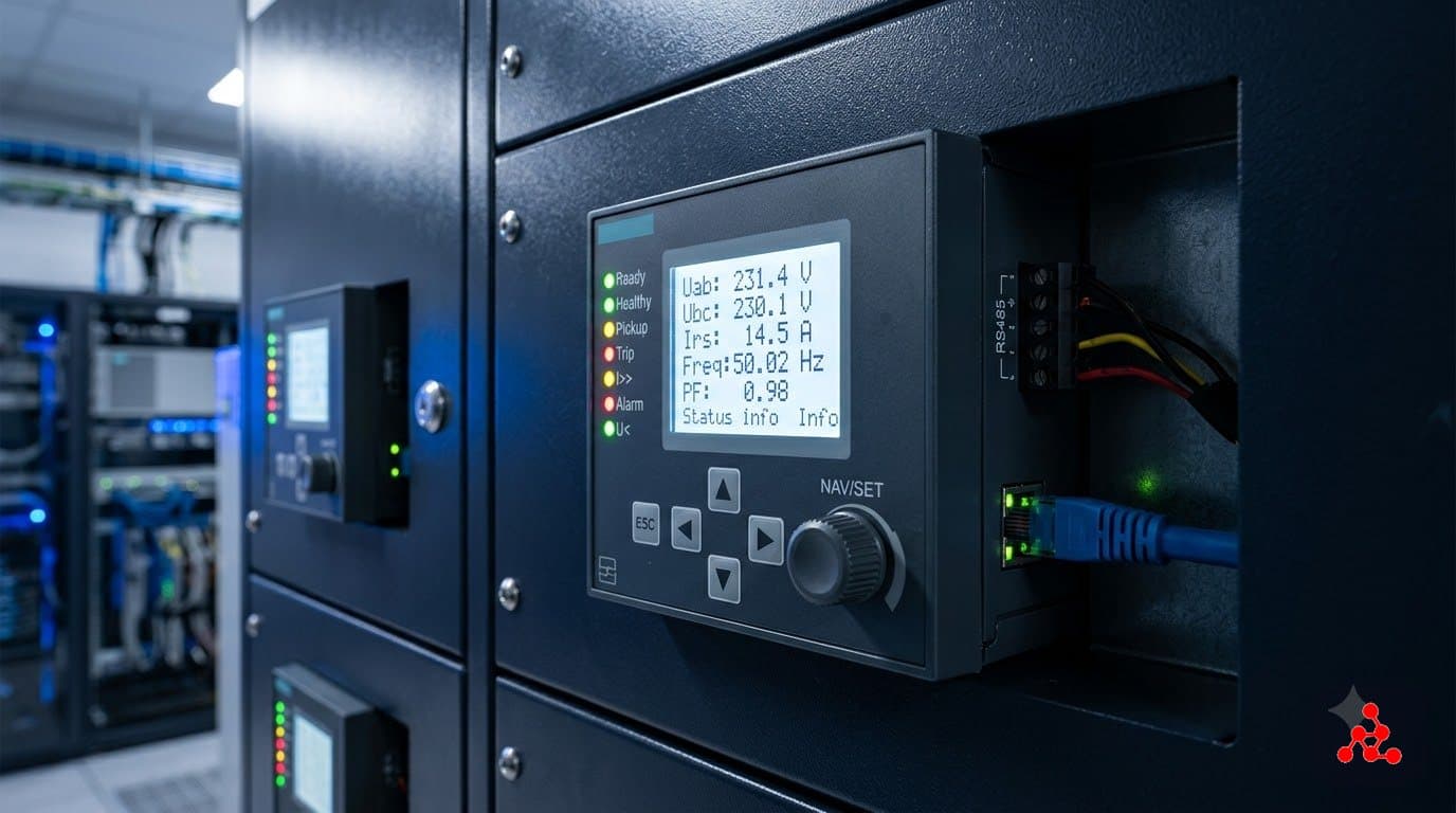
The goal
A fault should clear quickly and cause the smallest possible outage. In a redundant data center that also means a fault on one path must not trip the other. See protection relays.
The method
- Get the fault levels at each board from the short-circuit study.
- Plot the time-current curves of each device from the load up to the source on the same graph.
- Set pickup and time settings so downstream curves sit below and to the left of upstream ones, with a margin set by the device characteristics.
- Check that device settings still protect the cable and equipment (thermal withstand) and do not trip on motor starting or transformer inrush.
- Record the settings and issue them for commissioning.
Common tools
- Adjustable settings on breakers (long-time, short-time, instantaneous, ground fault).
- Zone selective interlocking where time grading alone leaves long clearing times.
- Software such as ETAP to plot and check curves.
Common mistakes
- Coordinating with default settings instead of verified ones.
- Ignoring the fault level range (maximum and minimum).
- Setting for selectivity without checking cable protection and arc-flash energy. See arc flash basics.
Written by the Vision Matrix Institute editorial team. Worked examples use stated, illustrative assumptions; check them against your project data, the applicable standards and manufacturer datasheets before use.
Frequently Asked Questions
What is protection coordination?
Setting protective devices so that the device nearest the fault operates first and upstream devices remain closed, which limits the outage to the smallest possible part of the system.
What is a time-current curve?
A graph showing how long a protective device takes to operate at different fault currents. Curves of upstream and downstream devices are compared to check they do not overlap.
What is discrimination or selectivity?
The ability of the protection to isolate only the faulted circuit. It can be full (up to the maximum fault level) or partial.
What data is needed for a coordination study?
Fault levels, transformer and cable data, protective device characteristics and settings, and the load and motor starting data.
Want to learn this properly?
This topic is covered in depth in our Electrical Design – Data Center Specialist program.
Ask us on WhatsAppLearn to do this on a full project in the Electrical Design – Data Center Specialist program, or read the data center design guide.