
Protection Relays Explained
A CT and a PT only measure. Something has to look at those measurements and decide whether a fault is actually happening — that's the relay's job, and it's the piece that turns sensors into an actual protection scheme.
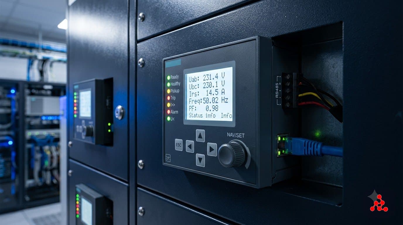
The decision-maker in a protection scheme
A CT reports current, a PT reports voltage — neither one decides anything. A protection relay is the device that takes those scaled-down signals, continuously compares them against preset thresholds, and decides whether the condition it's watching for — overcurrent, a differential fault, undervoltage, earth fault, and so on — has actually occurred. The moment it has, the relay energizes an output contact that closes the trip coil circuit, which is what mechanically opens the associated circuit breaker and clears the fault.
Three generations of relay technology
Relay technology has moved through three broad generations. Electromechanical relays — using physical coils, discs, and moving contacts to detect a fault — are the oldest, and plenty are still running reliably in older installations decades after commissioning. Static or solid-state relays replaced the moving parts with analog electronic circuits. Today's numerical relays, also called IEDs (Intelligent Electronic Devices), run the same protection logic in software on a digital processor, and typically bundle in metering, event and disturbance recording, and communication — commonly IEC 61850 — in a single unit. A modern data center switchgear lineup is almost always built around numerical relays specifically for that consolidation: one device doing the job that used to take several.
Reading a relay by its ANSI device numbers
Relay functions are identified on single-line diagrams and nameplates by standardized ANSI/IEEE device numbers, so any engineer can read a protection scheme without ambiguity or relying on a specific manufacturer's naming. A few that show up constantly in data center electrical design: 50 is instantaneous overcurrent, 51 is time-delayed (inverse-time) overcurrent, 87 is differential protection — comparing current in versus current out of a protected zone like a transformer or busbar — 27/59 is under- and over-voltage, 32 is reverse power, and 64 is earth/ground fault. Learning to read these numbers off an SLD, and knowing what each one is actually watching for, is one of the first real protection-design skills a new engineer builds.
Coordination: making sure the right relay trips
A single fault is usually visible to more than one relay upstream of it — which is exactly the problem protection coordination (also called grading) solves. Time delays and pickup settings are deliberately staggered so that, for a fault anywhere in the system, the relay closest to the fault trips first, and relays further upstream only step in if the closer one fails to clear it. Done well, a fault on one feeder takes down only that feeder. Done poorly, it can take down an entire bus that had nothing to do with the original fault — which is why coordination studies are a standard deliverable on any real protection design, not an afterthought.
How a CT, a PT, and a relay work together
In a typical scheme protecting a feeder or transformer: the CT clamps around the primary conductor and continuously reports a scaled-down current signal, the PT taps the bus and reports a scaled-down voltage signal, and the relay reads both, runs its protection logic against them in real time, and on a trip decision, energizes the breaker's trip coil to open it. Get any one link wrong — an undersized CT that saturates during a real fault, a PT with the wrong ratio, or a relay setting that doesn't match the actual fault current available — and the whole scheme fails to do the one thing it exists for.
Frequently Asked Questions
What do the numbers like 50, 51, 87, and 27 mean on a relay or SLD?
They're ANSI/IEEE device numbers, a standardized shorthand used on single-line diagrams and relay nameplates so any engineer can read a protection scheme without ambiguity. A few common ones: 50/51 is instantaneous/time-overcurrent, 87 is differential protection, 27/59 is under/overvoltage, 32 is reverse power, and 64 is earth/ground fault.
What's the difference between an electromechanical relay and a numerical relay (IED)?
Electromechanical relays use physical moving parts — coils, discs, contacts — to detect a fault condition, and many are still in service in older installations. Numerical relays, also called IEDs (Intelligent Electronic Devices), run the same protection logic in software on a digital processor, and typically bundle in metering, event recording, and communication (commonly IEC 61850) in the same unit. Modern data center switchgear is almost always built around numerical relays for that consolidation.
What is protection coordination, or 'grading'?
It's the practice of setting relay time delays and pickup levels so that, for a fault anywhere in the system, only the relay closest to the fault trips — not every relay upstream of it. Done correctly, a fault on one feeder takes out only that feeder, not the whole bus. Getting coordination wrong is one of the more consequential mistakes in a protection design, because it turns a small, local fault into a much larger outage.
Does a relay decide to trip on its own, or does something else make the final call?
The relay itself makes the trip decision — it continuously compares the CT/PT signals against its configured settings, and the moment a condition crosses a threshold for the required time, it energizes an output contact that closes the breaker's trip coil circuit, which is what mechanically opens the breaker. Nothing upstream of the relay approves that decision in real time; correct behavior depends entirely on the relay being configured with the right settings in the first place.
Want to learn this properly?
This topic is covered in depth in our Electrical Design – Data Center Specialist program.
Ask us on WhatsAppRead more: All articles or explore the Electrical Design – Data Center Specialist program, which covers protection and metering as a full module.