
Current Transformer (CT) Selection: Ratio, Burden and Class
A CT is selected on four things: its ratio, the secondary current, the accuracy class and the burden it has to drive. Here is how each is chosen, with a burden calculation that shows why 1 A secondaries suit long cable runs.
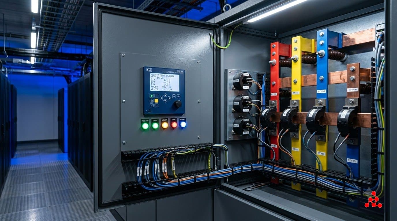
What you choose
| Choice | Rule of thumb |
|---|---|
| Ratio | Primary at or above the maximum load current; check saturation at fault level |
| Secondary | 1 A for long runs, 5 A for short; match the relay input |
| Class | Metering class for billing and monitoring; protection class (for example 5P20) for relays |
| Rated burden | At least the real burden of relay, meter and leads |
For what a CT does in the first place, see current transformer explained.
Ratio example
A feeder carries up to 300 A. A 400/1 A CT gives 0.75 A on the secondary at full load, which is comfortably within the relay input range. Check the protection class against the largest fault the relay must see, so the CT does not saturate before the relay operates.
Burden example
Illustrative example. A 2.5 mm² copper lead has a resistance of about 7.41 Ω/km. The CT is 50 m from the relay, so the loop (out and back) is 100 m, giving 0.741 Ω.
| 1 A secondary | 5 A secondary | |
|---|---|---|
| Lead burden = I² × R | 1² × 0.741 = 0.74 VA | 5² × 0.741 = 18.5 VA |
The lead burden alone is 25 times higher for a 5 A secondary. Add the relay's own burden (from its datasheet) to get the total, and compare it with the CT's rated burden. A 5 A CT on this run would need a much larger burden rating or thicker leads, which is why 1 A is the usual choice for long runs.
Checks
- Total burden is within the CT's rated burden.
- The CT does not saturate at the maximum fault current, using the accuracy limit factor or knee-point voltage from its data.
- Metering and protection cores are separate where both are needed.
- Secondary circuits are never left open while the primary is energised: that can produce dangerous voltages.
Common mistakes
- Choosing the ratio only from load current and ignoring fault current.
- Forgetting lead resistance in the burden.
- Using a metering-class CT for protection.
Related: protection relays, overcurrent relay settings and potential transformers.
Written by the Vision Matrix Institute editorial team. Worked examples use stated, illustrative assumptions; check them against your project data, the applicable standards and manufacturer datasheets before use.
Frequently Asked Questions
How do you select a CT ratio?
Choose a primary rating at or above the maximum load current, so the secondary current at full load is within the meter or relay's range, and check the CT will not saturate at the maximum fault current the protection must see.
Should I use a 1 A or 5 A secondary?
1 A secondaries create much lower burden in long secondary cables because the loss is I squared times R. 5 A is common for short runs, such as inside a panel. Match the relay or meter input.
What do metering and protection classes mean?
Metering classes (such as 0.2 or 0.5) describe accuracy at normal load currents. Protection classes (such as 5P20) describe accuracy up to a multiple of rated current, which keeps the CT accurate during a fault.
What is burden?
The load connected to the CT secondary, in VA or ohms: the relay or meter plus the connecting leads. The CT's rated burden must be at least the actual burden, or it can saturate.
Want to learn this properly?
This topic is covered in depth in our Electrical Design – Data Center Specialist program.
Ask us on WhatsAppLearn to do this on a full project in the Electrical Design – Data Center Specialist program, or read the data center design guide.